
Accurate measurement of oceanic pressure gradients is extremely challenging because the associated pressure differences are for many applications very small. For example, pressure gradients associated with the wind-driven circulation over continental shelves, on time scales of days to weeks, correspond to pressure differences of a few millibars (1 mb is equivalent to about 1 cm of water) over separations of about 100 km. Since pressure sensor accuracy is generally a function of full range, a sensor that can be deployed in 100 m of water (typical shelf depth) must have an absolute accuracy of about 0.01% of full range.
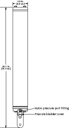
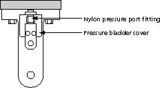
To estimate pressure gradients over the North Carolina inner shelf as part of the CoOP inner-shelf field program (Butman, 1994) we purchased eight Seagauges. Seagauges are relatively new, self-contained instruments for measuring absolute pressure and are manufactured by Sea-Bird Electronics, Inc. of Bellevue, Washington. This note describes evaluation and modification of the Seagauge pressure ports done at Woods Hole Oceanographic Institution (WHOI) prior to deploying the instruments in the CoOP field program.


The results from these initial flume tests indicated that a new pressure port design was needed to minimize flow effects on the pressure measurement. We chose a parallel plate design for the new pressure port based on tests done for barometric pressure sensors by Gill (1976) and discussions with J. Candela (WHOI) who had used a parallel plate port previously with pressure sensors similar to the Seagauges. Based primarily on extensive wind tunnel testing done by Gill (1976), we chose the following characteristics (Figure 3). The parallel plates were separated by 0.5" with 3 spacers. A spiral of 36 grooves per inch was put on the plates and the outer edge of the plates were chamfered 15 degrees toward the inside of the plates to smooth out the flow and reduce the pressure dependence on flow speed.
Material choice was also a consideration when designing the pressure port. A copper nickel alloy was chosen for its antifouling and corrosion resistance properties, as well as machinability. There was no significant biofouling of the instruments during the four-month (August to December, 1994) CoOP inner-shelf field study indicating this was a good choice of materials.
A new mounting block to accommodate the pressure bladder was designed and fabricated out of delrin. The parallel plate assembly was attached to the mounting block via a piece of threaded fiberglass tubing with a 1/8" diameter hole through the mounting post to allow the pressure to get to the pressure bladder.
The flume tests were repeated with the new pressure port for flow speeds of 6, 18 and 38 cm/s. The variation in pressure was about 0.2 mb with higher pressures at the lower flow speeds. The only dependence on instrument orientation was whether one of the three spacer posts (holding the parallel plates apart) was oriented into the flow. Pressures were typically 0.1 to 0.15 mb higher with a post oriented into the flow than when the gap between posts was oriented into the flow.
The dependence on both flow speed and the orientation of the posts are tenuous because the experimental uncertainty is about 0.1 mb. However, these results indicate that the parallel plate port reduced flow effects on the pressure measurements by about a factor of 10.
(1) Butman, C. A., 1994. CoOP: Coastal Ocean Processes Study Interdisciplinary approach, new technology to determine coupled biological, physical, geological processes affecting larval transport on inner shel. Sea Technology, 35, 44-49.
(2) Gill, G. C., 1976. Development and testing of a no-moving-parts static pressure inlet for use on ocean buoys. NOAA Data Buoy Office, Bay St. Louis, Miss. 43 pp.
(3) Wearn, R. B. Jr., and N. G. Larson, 1982. Measurements of the sensitivities and drift of Digiquartz pressure sensors. Deep Sea Research, 29(1A), 111-134.
Craig Marquette is an Engineer and Dr. Steven Lentz is an Associate Scientist in the Physical Oceanography Department at the Woods Hole Oceanographic Institution.
 Return to UOP Homepage