file: asimet_module_ops.html
10 May 2007
ASIMET MODULE OPERATIONS
The ASIMET main processor board (C530) operates in either RS232 or RS485 upon power up depending
on where power/comms is connected and the position of a jumper. See the
RS485 note at the end of this document for info on RS485
operation.
Refer to Humidity Module Command Set for a typical full command descriptions.
The latest versions of documentation for ASIMET (and other instrumentation) are
available online at: http://buoy3.whoi.edu/UOPinstruments/frodo/versions.html
Getting Started
The following equipment should be available:
- Computer running a terminal program (ProComm Plus or equivalent) with RS232 output set for 9600, N, 8, 1.
Run with caps-lock ON.
- Power supply with output of 12-15 vdc and capacity of 100 ma. Make sure that the polarity
is correct; otherwise the module may be damaged!. A meter in series with the module power
supply is recommended to monitor the supply current (about 3 - 6 MA is typical after startup).
- RS232 to RS485 converter: See the RS485 note
at the end of this document for info on RS485 hookup.
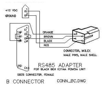
- Connector to power / comms - see drawing of
RS485 adapter cable
Use Molex connector as noted - (03-06-1044 male shell, 03-06-2044 female shell,
02-06-5103 female pins, and 02-06-6103 male pins. HTR1719C tool required).
- Module C530 RS232/RS485 mode configuration. The C530 board is placed into the desired mode
upon power up based on the input connector used and the position of jumper JP2. The unit must
be opened up to make this change.
- RS485 mode: JP2 is connected to pins 2-3 (closest to connector P2); the power/comms
cable connects to P2.
- RS232 mode: JP2 is connected to pins 1-2 (closest to connector P1); the power/comms
cable connects to P1.
- Refer to the drawing of the board for the proper configuration. Note that JP1 (near
the center of the board) is normally set for pins 2-3 for RS485 comms to the sensor
front end board if applicable.
- NOTE: for adapter cables, see drawings of
RS485 adapter cable and
RS232 adapter cable.
A module should always be powered up and communicated with on the bench prior to connection
to a system or when checking operation and trouble shooting. Make sure that the +12 Vdc is
connected to the proper connector pin, and that the terminal is running at the proper protocol
(9600, N, 8, 1). The idle current drawn should be in the 2 to 6 milliamps range depending on the module,
somewhat higher for SONICWND.
Communications
The ASIMET (like IMET) has a communications protocol based on the SAIL (Serial ASCII Interface Loop)
protocol developed at Oregon State University. The module is interrogated by sending commands with the
following format (always with capital letters):
PREFIX    3 char TYPE    2 digit NUM       COMMAND
  #          XXX            nn              X(xx)
where:
- PREFIX is always #
- TYPE of:
- BPR = Barometric Pressure
- HRH = Relative Humidity / Air Temperature
- LWR = Longwave Radiation
- PRC = Precipitation
- SST = Sea Surface Temperature
- SWR = Shortwave Radiation
- WND = Wind Speed and Direction
- NUM of:
- 2 char of 01, 02, 03 etc.
- COMMAND of:
- A = Address acknowledge
- C = Output calibrated
- H = help
- I = ID information
- L = Calibration header Info
- T = Test data (usually 1 sec rate)
- U = EEPROM Update mode (requires password of "OK")
Refer to the individual command set for each module for details.
REMEMBER: the latest versions of documentation for ASIMET (and other instrumentation) are
available online at: http://buoy3.whoi.edu/UOPinstruments/frodo/versions.html
RS232 to RS485 converters
- Black Box, Inc. sells 2 converters that work well. The first is a
PCMCIA/RS485 port (Part# IC114A, $199). This unit works well on laptops with PCMCIA slots but
does not suppress the transmissions (you see two sets of what happens).
- The second is a standalone unit (Part# IC108A, $259). This unit works well on the bench.
The settings for the IC108A standalone unit are as follows (* indicates default):
  XW1A		DCE *
  W8		B-C	2-wire
  W15		A-B * RTS/CD enabled
  W5		A-B *  RTS/CTS delay normal
  W9		RTS/TCS delay	C*	0 msec
  W17		D	0.7 msec	time driver remains enabled after a low-to-hi transition
  W16		B * 	0.1 msec	Turnaround delay
  S1		OUT * 	Normal
  S2		OFF *		RS-485 receiver Unterminated
  S3		OFF *		Line Bias Off
  TB1:
     term 1, Rx	B+ (connect to 3, Tx, B+) to the +485 (orange)
     term 2, Rx	A-  (connect to 4, Tx, A-)  to the -485 (brown)
     term 3		Tx	B+
     term 4		Tx	A-
- An RS485 adapter cable connects from a DB25 Male RS232
on the Black Box IC108A to the 4-pin Molex that terminates the standard VMCM2 power/comms cable.
This adapter includes a 2-pin Molex connector can mate to a standard VMCM2 battery or power supply
adapter cable.